3D For VFX – Week Five

This is the final week before product submission. The class work from last week was a render of 3D model we were working on. In the morning, we ran through submitted renders of our projects with our class tutor.

First test render of the 3D object

This first render I submitted has a lot of issues that need to be addressed. Putting the technical faults aside, composition wise, the monorail tracks were not laid out with aesthetic sense in mind. While it would be logical to have a station above the current DLR stop for interchange, this would be difficult to create, as lighting in the scene would change drastically. For this reason, I have decided to change the direction of the tracks, which now make a cross intersection few meters away from the lift shafts.
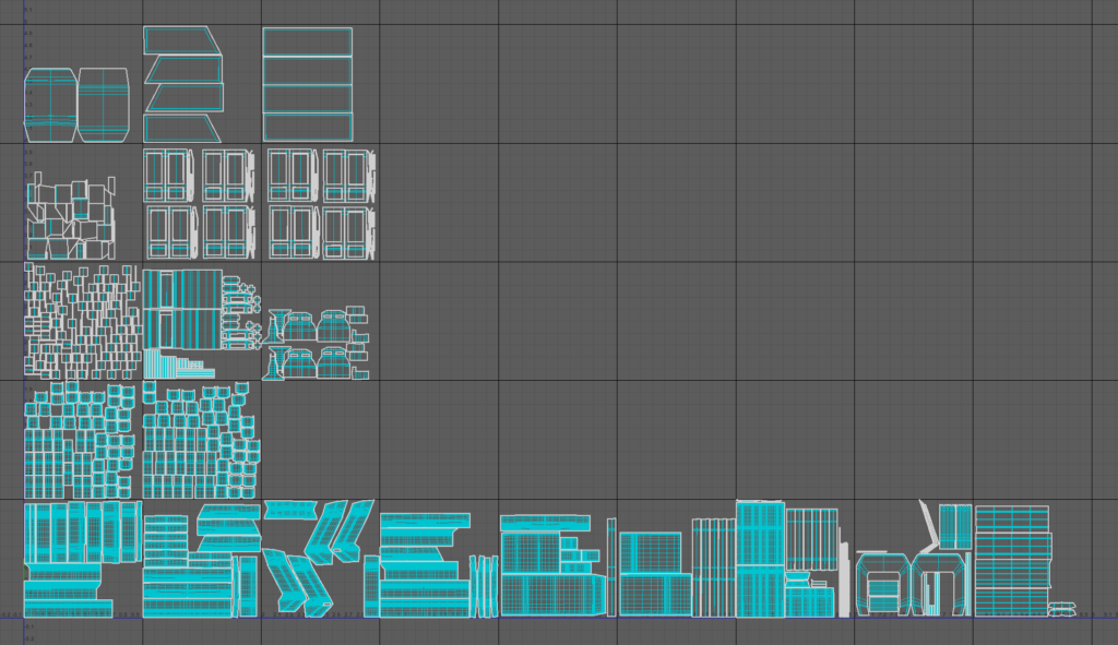
Train UV Unwrapping

In the afternoon, I was unwrapping UVs for the train model. The model was fairly complex, and the UVs took around 5 hours to create. I used multiple UDIM tiles, and intend to texture in 2K.

Train UVs

Track UV Unwrapping

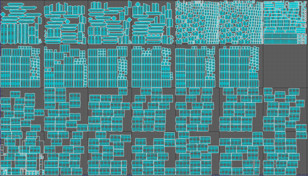
This was a lengthy process, as the UV shells were really heavy to work with. However, in the end I was satisfied with the result.

Project Pipeline

  • Timeline export from Nuke as .png image sequence for use in 3D Equalizer 
  • Sequence export in ACES for better results with colour and dynamic range, also simplifying cross application workflows (all software uses the same colour space, eliminating differences in materials Substance Painter to Arnold etc) 
  • 3D Equalizer track and solve with exactly surveyed points using measurements from Google Earth and wikipedia (track gauge, platform length, elevator shaft width) – all of these measurements used in maya to scale the scene as well.
  • 3DE to Maya (.mel export) of point cloud and solved camera with dewarped (undistorted) footage, using frame offset to offset the sequence and image scale in maya to compensate for the added pixels from overscan, also using lower bitrate .png files for maya to play more smoothly
  • Creating proxy geo in Maya for better scene orientation and later use (masks, roto)
  • Modelling and texturing in different maya projects for better scene and asset management, then referencing these scenes in the main maya project
  • Using motion paths in maya to lay out the track
  • UV creation using udim tiles and texel density to properly scale all objects to scene scale, optimizing all of this for further smoothing (adding edge loops where needed etc.) Distributing UVs to udim tiles depending on the material
  • Creating UVs before duplicating objects and laying some of them in the scene (pillars, track, train, etc.)
  • Catclark smoothing on render with Arnold parameters to keep work in viewport comfortable
  • Maya to substance painter: .fbx smooth or original mesh export depending on the shape and LOD needed, creating materials as PBR Metallic Roughness
  • Baking texture maps for each model, minding resolution – LOD relation, using own settings (learned in class) for baking to increase quality of materials
  • Creating materials with references to real world materials
  • Adding textures and individual details from real world references on top of materials and generators
  • Anchor points for surface effects, wear & tear
  • Exporting textures from Substance Painter in targa format
  • Applying these textures as UDIMs to aiStandardSurface material in Maya
  • Lighting using Arnold lights and HDRIs
  • Lookdev – setting up maya layers, AO, lighting setups and preparing the scene for rendering 
  • Setting up rendering AOVs – multichannel exr with render and utility passes
    • Diffuse – Direct,Indirect, Albedo
    • Specular – Direct,Indirect
    • Transmission pass
    • Coat
    • Alpha pass for the geometry
    • Depth pass / Z
    • N Pass
    • P Pass
    • ID Pass – track, and trains separately – render layers
    • Motion Vectors – render layer
    • Shadow Mask
    • Shadow Diffuse
    • Ambient Occlusion – render layer
  • Using ACES colorspace to render image sequence for easier integration in Nuke and richer colour and luminance information
  • 3DE to Nuke Lens distortion node export
  • Slap comp in Nuke for final submission, leaving  advanced composting for next module.

3D For VFX – Week Four

Train texturing

This blog post is about train texturing process in Substance Painter. The model was imported mostly as low poly mesh, with the exception of floor and frame, which were a smooth mesh conversion from Maya. In total, there were 20 2K UDIM tiles.

Reference Images

Frame Material

HVAC Unit Material

Creating the textures

For the most part, I used procedurals to generate my textures. When creating procedural textures, Substance Painter requires mesh maps, which are baked within the software.

Mesh Maps generated in Substance Painter

First Render

This is the first render with textures exported from Substance Painter. Although I like how the train looks from up close, certain details (roughness variation and normal maps which deform the surfaces) do not seem present from distance. This will be fixed in the next iteration. Also, normal maps on the glass are way too strong, which can be seen in distorted reflections. I will also add more lime and dark blue shell foils on the frame, in accordance with the livery of this service. I believe this will break up the flat pattern of the frame and add more detail.

Second renders

After adding lime and dark blue stickers plus some roughness grunge and smudges, I was happy with how the textures turned out. The glass reflections now look okay, however, the poor bit depth of the normal maps make the window geometry look unnatural.

3D For VFX – Week Three

Modeling the track

Figuring out the proper modelling technique for the track was a difficult task. I considered using MASH network, extruding face along curve, making a NURBS curve and extruding it, but all these solutions involved a massive amount of manual work to add details, UV unwrapping not even considered. In the end, I decided to use a motion path technique.


Track References


Modelling the base element

I began with a cube primitive, then added mesh loops which define the silhouette of the track. Then, I deleted the faces which create the cavity in the middle, where the train’s motors will go. I bridged the edges to close the model again, and then deleted the front and back faces, as the track will be replicated.

For the distribution along a curve, I followed a tutorial on how to create a roller coaster track in Maya. In theory, the end product of the tutorial is very similar to my monorail track.

The technique explained in this tutorial is as follows: using a motion path which constrains the desired object on to a curve. This creates an animation, converting it to actual geometry is done by using animation snapshots. Animation snapshots make a visual representation of all places the object appears at per each frame of the animation. This snapshot is then converted into mesh by using Mesh – Combine, which combines all the different parts into one polymesh. Finally, joining all these individual pieces is done by bridging the edges of the model. My final track had approximately 100 individual pieces I had to manually join. For this, I mapped Wacom Express Keys to Maya commands – G – repeat last, and Ctrl + Del which deleted the edges. I also had to disable construction history for this part, as it was slowing performance down drastically.

Final track section
Final track layout

After joining the track sections together, it was time to lay the columns out. I laid them out in the same distance apart from each other, keeping in mind the position of objects in the original plate. When this was finished, I modeled a basic fence and wire sections, which I duplicated with motion paths over the tracks. These models were not textured at all, only shaded with AiStandardSurface and some Roughness Metallic values.

Train modeling

I began with a cube primitive, which I then made holes in and extruded the frame. I used a reference picture for the model, however only for the right part of the train. The frame is used as a smooth mesh on rendertime, with three catclark subdivisions.

Reference Image
Train modeling iterations
Train final model with textures and track

3D For VFX – Week Two

This week, I began tracking my DLR shot. The following days, I was focusing on this process.


Loading the footage

Loading the footage into 3DEqualizer

I exported the footage first as a .dpx sequence, which I brought into 3DEqualizer. I found out this was a wrong decision, as .dpx colour space is different from SRGb and thus it did not display correctly. That is why I used .png sequence later, which worked well.

Tracking the camera

Click to expand.


I used about 150 manual tracking points in conjunction with filtered autotracked points. The result was very good in the first stage, so the only thing I focused on in the next stage was calculating the focal length and lens distortion properly. I used the Parameter Adjustment Window to adjust these details. First, I used wide range and brute force method to guess the numbers, and then Fine with Adaptive method. The results were good and the lens distortion was not visible afterwards. Then, I exported this as a .mel file for use in Maya, and rendered the first matchmove playblast, which I included below. I also modeled some geometry, which is I will use later on in comp for rough roto work.

Survey points

Survey points indicate the scene scale and the position of scene origin (point that has zero X,Y,Z values). I used data from Google Earth to survey the camera. It works by clicking on the point, then choosing ‘Exactly Surveyed’ under survey type. The point in the image would be my scene origin.

Survey point settings

After setting the scene origin, I selected another point which I assumed would be further back on Z axis. I roughly estimated the distance of the point, lined up the horizon line correctly and exported the scene into Maya. I then used measurements from Google Earth to scale my scene to real world scale inside Maya.

Second survey point line up, horizon line correction

First matchmove submission

First Matchmove playblast

3D for VFX – Week One

Module introduction

On the first day of this module, we were introduced to the course. Together with the class, we went through the brief and what we need to submit. The assignment in this module was to create a 3D object, either a building or a machine, and to seamlessly integrate it into moving backplate. This means that the render had to be as photorealistic as possible – the lighting, texturing and overall style should fit the plate to the artist’s best ability. The software used in this module would be as follows – Nuke for clip conversion and image sequence export, 3DEqualizer for camera tracking, match-moving and camera solve export, Autodesk Maya for 3D modelling and UV editing, Substance Painter for texturing and shading work, Arnold Render under Maya for rendering, and finally, Nuke once again for final slap comp that will be submitted as the end product for this module. Furthermore, the product we create in this module will be used in the next module, VX5002 – Compositing for Visual Effects.


Introduction to 3DEqualizer

3DEqualizer is one of the best 3D tracking solutions on the market today. While the UI and environment can seem a bit daunting at first, the program is very intuitive and the workflow is well designed. All quirks and inconveniences aside, it has the best algorithms and coding for solving camera and making 3D tracks, as well as calculating lens distortion, focal length and sensor size if the department does not have these details on hand.

Why is matchmoving needed?

Matchmoving is needed if there are any shots that require putting 3D/2D objects into a 2D plate. An artist has to manually track makers or patterns on the plate in order for the program to properly solve the camera. The easiest camera moves to track are the ones where parallax is obvious and depth of the environment being shot is clearly visible. A proper 3D camera track provides an artist with data about camera movement – what is the position of the camera at a given time, what is its orientation and physical details of lens and camera sensor. With this data, the artists can then place their objects in the 3D scene using 3D package of their choosing.

Sample matchmoving reel from one of Escape Studios students

Tracking in 3DEqualizer

3DEqualizer requires at least 6 tracking points to be present in the shot at a given frame in order to get a camera solve. Creating tracking points is simple – control + left mouse click creates a tracking point, which then needs to be set to either pattern or marker tracking point. However, as you would imagine, if you have more tracking points, you can get a more accurate camera solve. A higher number of tracking points also help to better calculate the lens distortion profile, focal length and filmback height.

Solving 3D camera in 3DEqualizer

When solving camera, 3DEqualizer calculates the position of the camera using the position of tracking points on the plate and distributes them in 3D space based on the difference in their motion (speed, scale change, parallax, etc.) relative to the camera. Calculating a camera is done through ‘Calc’ – ‘Calculate all from scratch’ or a handy Alt + C shortcut.

3D camera tracking is an iterative process. It usually takes many small steps to complete. After solving the camera, 3DEqualizer displays a deviation curve for each point used to get the solve. What this means is that when a camera is 3D solved, each tracking point should stay exactly on the same coordinates in 3D space. Any deviation will be displayed as a curve in an XY graph, where the X field is the current frame number and the Y field is the deviation value in pixels. All of the curves for each point are then averaged into a single curve, which gives the user an idea of how good their track is. With this graph, the user can easily remove bad tracking points and get a better average curve.

Camera calc window in 3D equalizer

Plate selection and 3D proposal preparation

On this day, we selected three plates we had an idea for. We were supposed to make a 3D proposal for three shots we intended to work with.