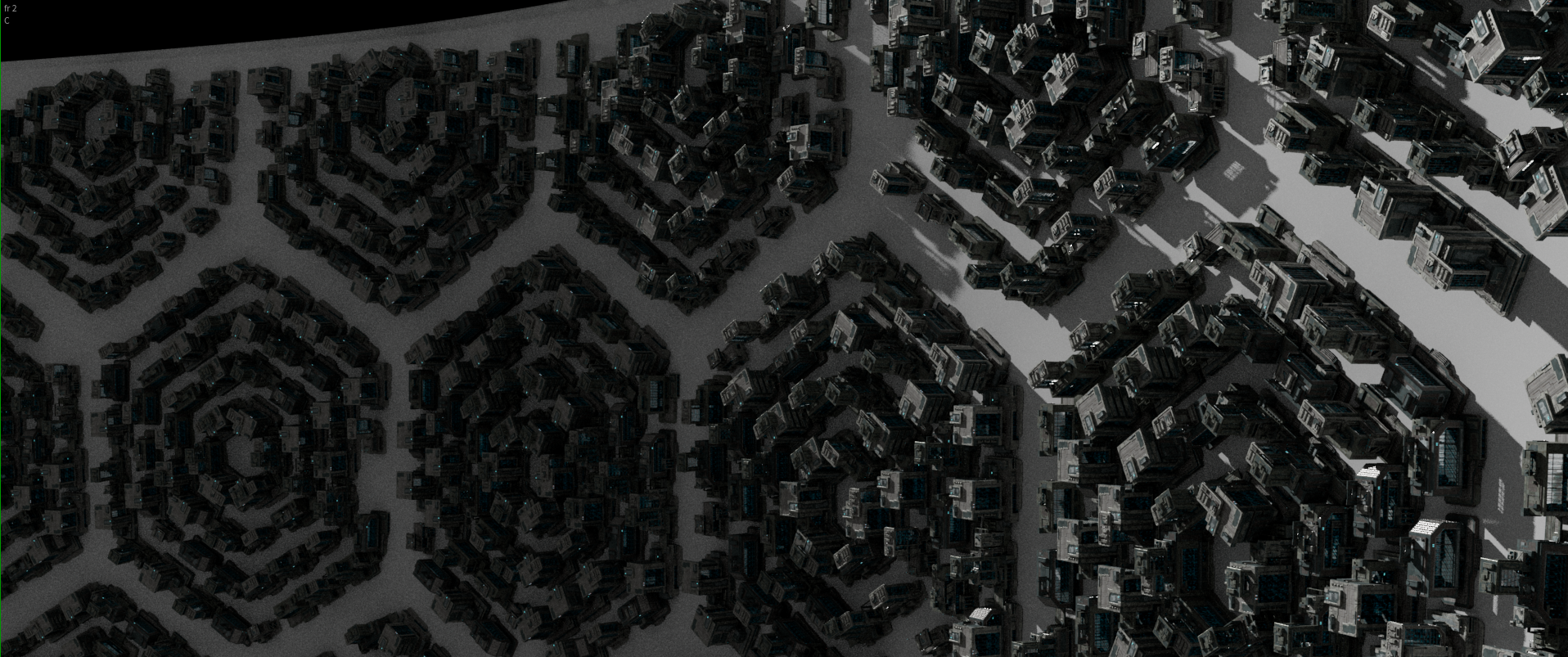
I am using Arnold for Houdini with ACES to render the scene. Lighting for the final render is an IBL HDR lighting, a directional light to represent a star, and a few thousand Arnold mesh lights. The mesh lights were used to imitate sunlight inside the ring, and to create light inside the elevator shaft windows.
Mesh lights Fake day light from Mesh LightsStarfield IBL LigtingMesh lights from elevator shafts
Houdini camera flipbook
The camera move was created using WylieCam using my phone gaffer-taped to a handheld rig.
Shaders
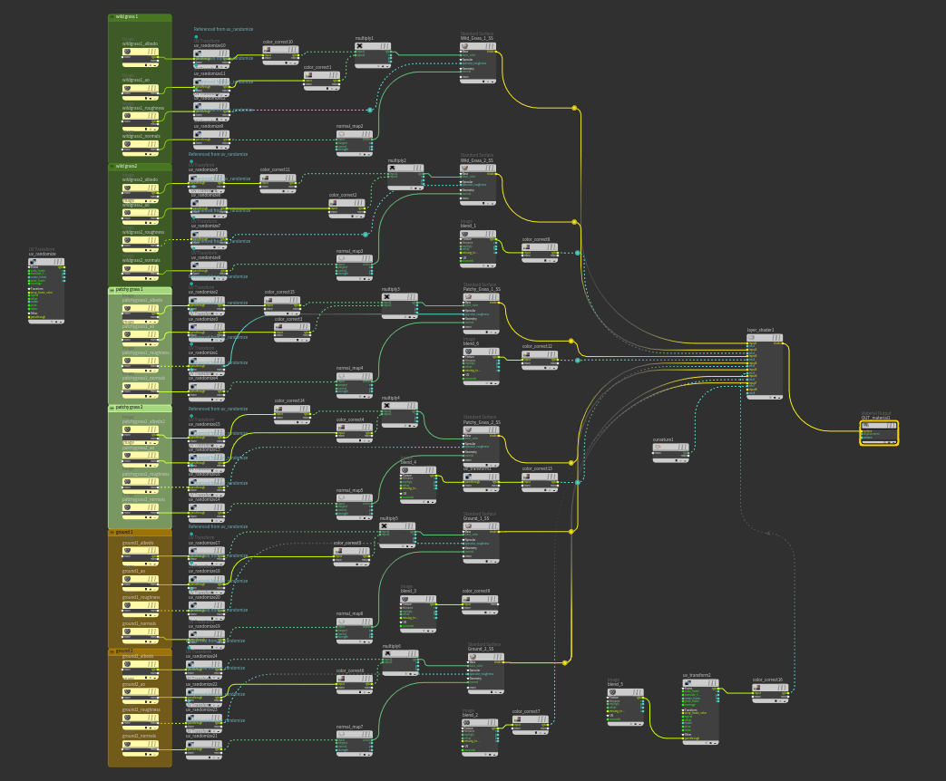
Most of the shaders were tileable textures from Megascans, interpolated using grunge maps and tiled onto the surfaces either by using UVs I created in Maya, or by using triplanar projection.
Arnold shader for the ground plane
For the houses and trees, I recreated the shaders in Houdini and re-applied them using Python.
Although the final slap-comp I created has some issues (e.g. fireflies), I am satisfied with the result I achieved during this module.
In total, the scene I sent to the render farm consisted of approximately 215000 objects. Most of these were instances of houses, trees, the glass roof, windows and other models. I used SideFX Houdini to lay out the points, and then copied the instances to them.
Glass roof
The glass roof was the setting stone for the instances underneath, as it set a proportion of how big the blocks of houses were. Naturally, I laid it out first. I created a tube sop, and rotated every second row of it to create a base point cloud for instancing. These instances were packed in the CopyToPoints SOP.
Base points used for instancing
Instanced object
Instanced object
Houses
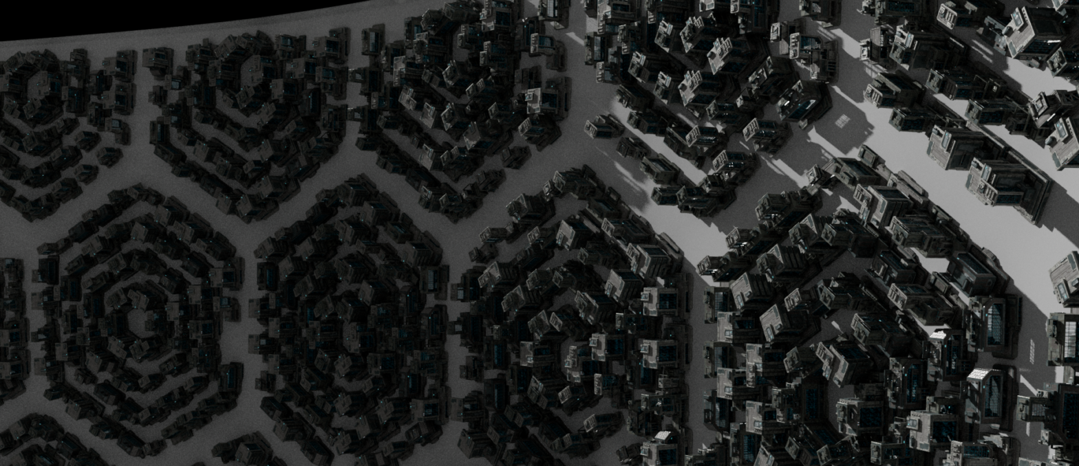
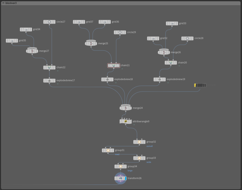
There are 21 variants of the houses in four categories – small, medium, wide and large. They were imported from a kitbash in Maya. I used VEX to categorize them and to create a variant attribute, used when copying the houses to an appropriately scaled lot. The lots were created using Chain SOP, which deformed a simple grid on a hexagonal curve. The scale of the houses copied was determined by hand using groups, however I imagine this could have easily been set up procedurally.
Block variant
Block variant node setup
The result using multiple lots
These lots were projected on the ground plane using Ray SOP, and cleaned up of pieces that contained less than four points per primitive.
For randomizing which variant of the house from its respective category goes on its lot, I used this VEX snippet:
on the point groups I created earlier. This randomized the variant number, which the CopyToPoints SOP took as an input when instancing.
CopyToPoints SOP operationAn early render test of house instancing.
After a few iterations I was happy with the result.
Trees
I used a similar approach when loading the trees and categorized them based on their size. The only difference is that I used the AttributePaint SOP to create a mask for instancing.
AttributePaint maskInstanced trees
A VEX snippet I found myself using repeatedly while instancing:
for (int i = 0; i < @numpt; i++) {
f@posy = @P.y; vector a = set(0,@posy,0);@N = normalize(a-@P);
 }
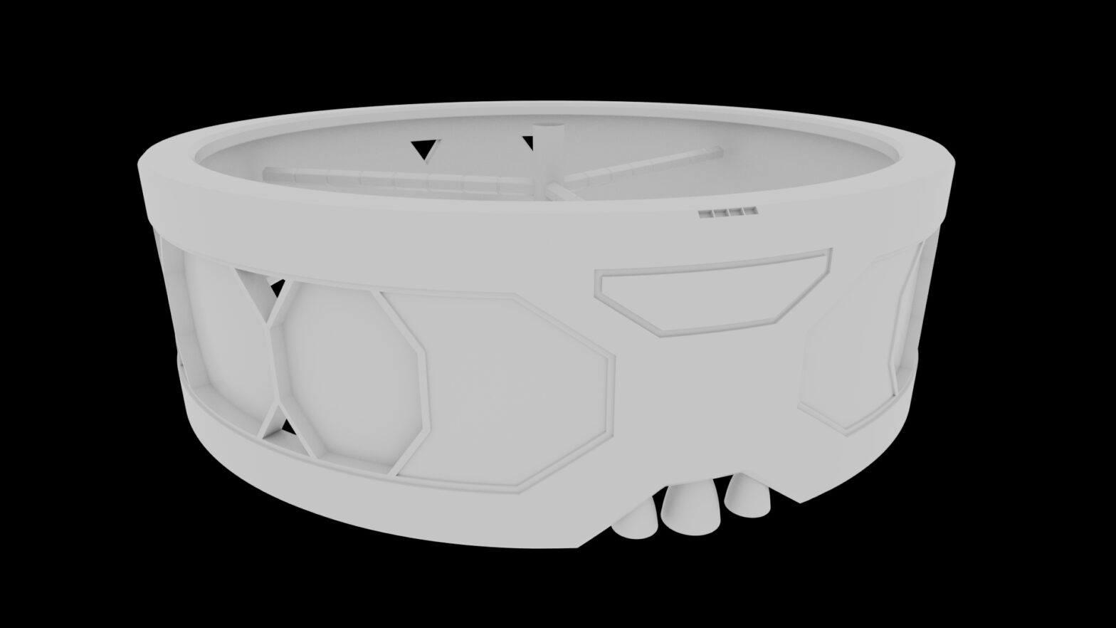
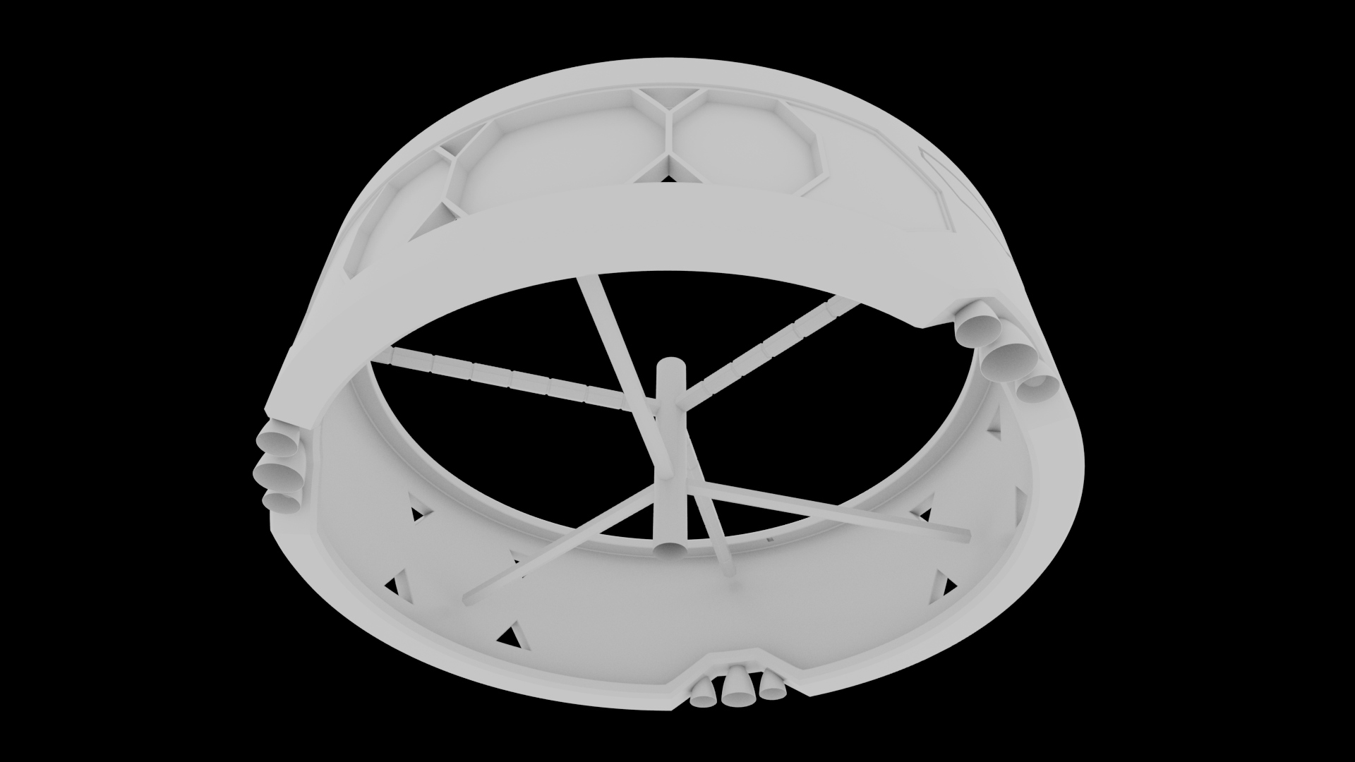
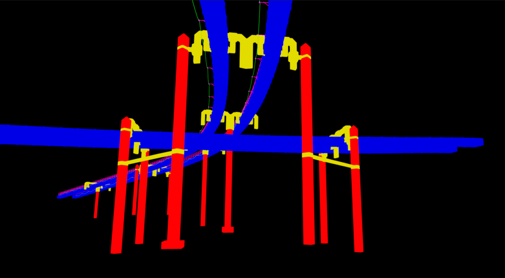
The shape of the ring is a simple cylinder with three cut-outs, allowing for radial symmetry. These cut-outs serve as a place for a drive module which propels the ships when in space. These modules are fully modular – able to manoeuvre and orient themselves to suit any configuration. The outer part of the ring has a hydroponics section ensuring sustainability and docking space for ships that enter a planet’s atmosphere and go around, while the inside is where the flight duration habitats are. The centre part is what connects these rings together, provides transport corridors and ensures spin gravity. It is connected to the ring with six elevator arms, each with a length of about 747 metres. Most of the modelling work is done in Autodesk Maya.
Outer side of the ringInner side of the ring
Ground plane detailing
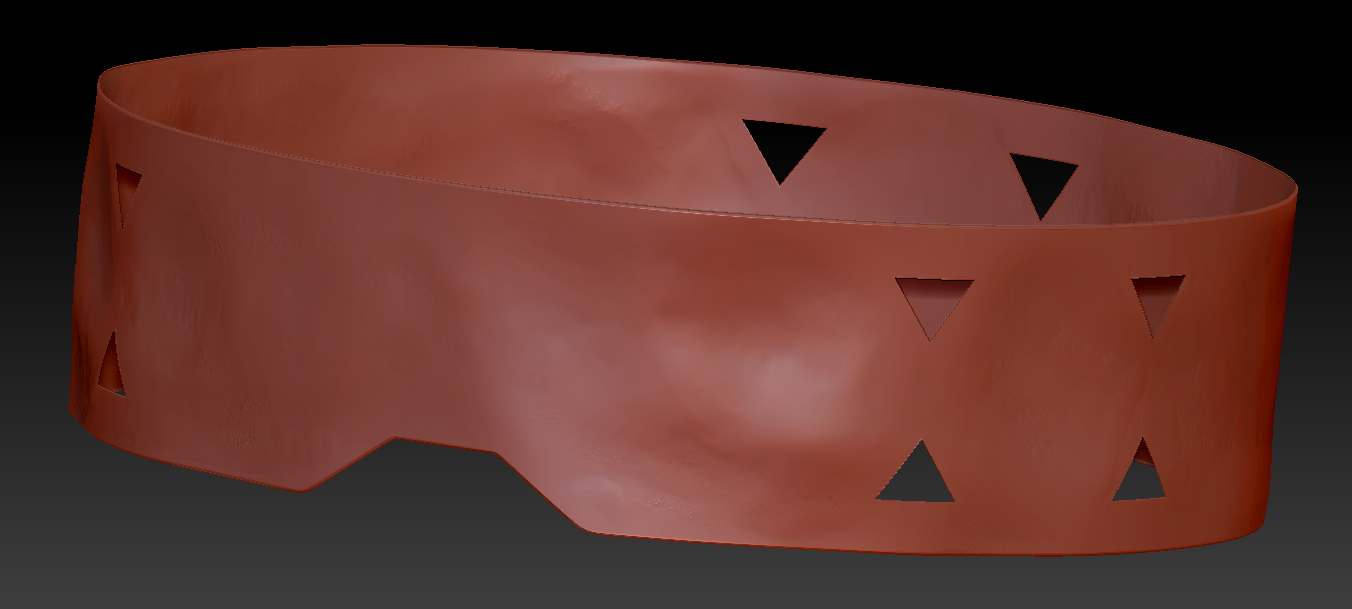
The ground plane was exported to zBrush for detailing. I deformed the surface to mimic small hills and add some variation.
zBrush detailing
UV Mapping
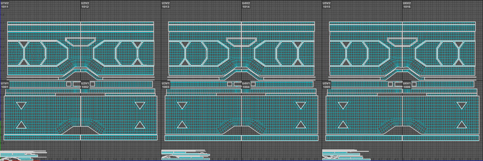
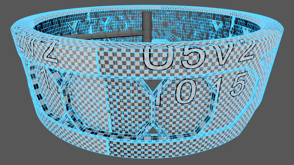
I unwrapped most of the ring in Autodesk Maya, while the elevator shafts were unwrapped in SideFX Houdini later. I used a cylindrical projection for most of the parts to keep the UVs consistent. I split the main geometry of the ring into three pieces, as it was modelled that way, and scaled them up to take four UDIM tiles per part. I have then roughly laid out the UVs so that they line up along the seams where possible.
UV’s of the ring geometryUV Checker displayed on the ring
A 3D asset is required as a submission for this module – CR6001. It is to be modelled, textured, lit and rendered along with turntables and other objects to support the submitted asset.
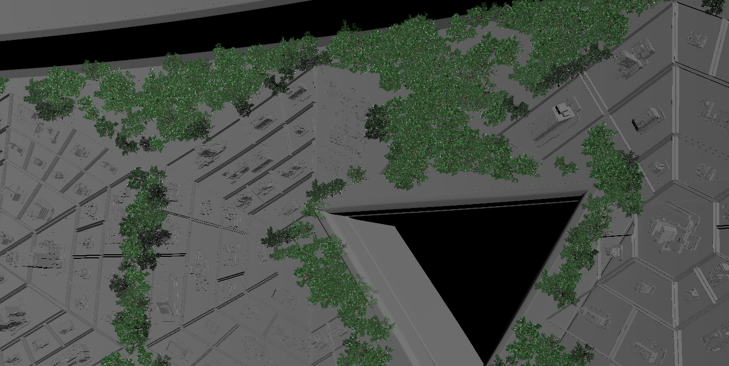
Large-scale scenes and environments and the process of creating them has always caught my attention. For this module, I decided to make a 3D environment – a version of O’Neill cylinder, with houses and trees onboard.
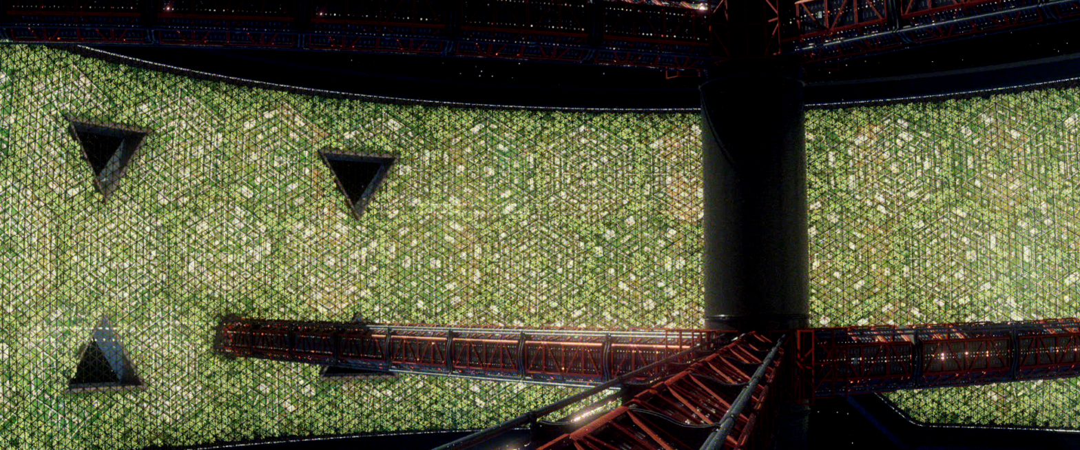
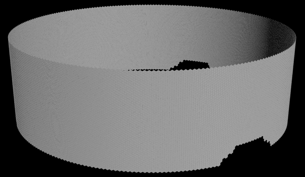
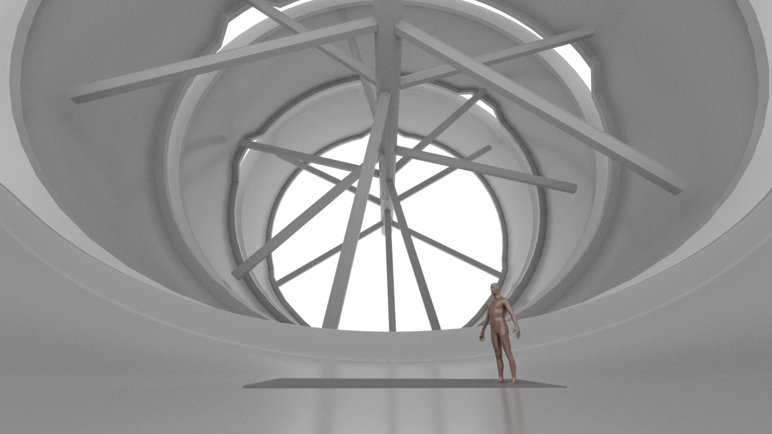
My proposal for this module was to create a fully computer-generated environment – a set of four rings making the cylinder mentioned above.
A wide angle shot of the proposed cylinder with a human pose to compare sizeAnother shot of the cylinder. Notice the dark dot near the first ring’s further wall – it is the same size as the plane in the image above.
The idea behind this concept – and any other O’Neill cylinders – is to serve as a settlement ship. It would provide spin gravity similar to that on earth. In my concept, the two pairs would separate along the way where habitable worlds have been discovered. They would then burn towards two solar systems in a pair, later separating once more. This way, the four stack would be able to settle on four different worlds.
Job specs research
As a part of this module, I researched into certain job specifications and disciplines my project would cover. I came to conclusion that 3D Generalist and 3D environment roles would best suit the proposal.
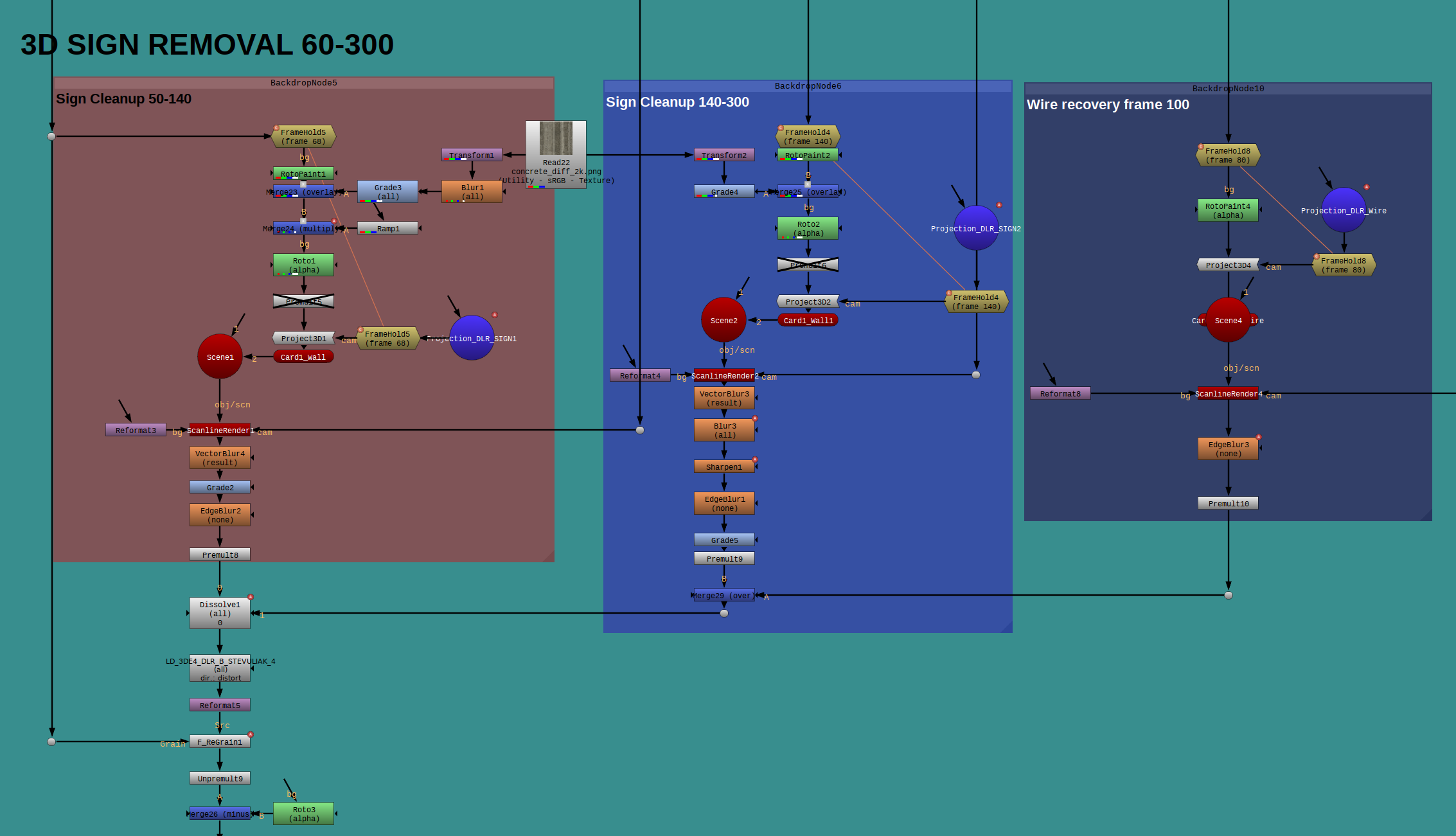
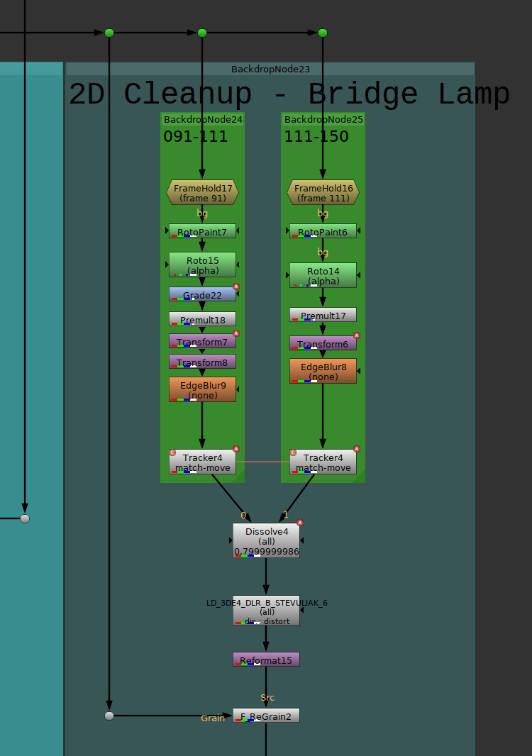
A 3D cleanup is different from a classic 2D cleanup. In 3D, we use match-moved camera to stick clean patches onto the original plate. A typical 3D cleanup involves a 3D camera (I used my 3DEqualizer match-moved camera from VX5001), then freezing the position using FrameHold, RotoPaint as in 2D. After this, the clean patch is re-rendered using the match-move camera without frame hold. My 3D cleanup consisted of three patches, so I used a Dissolve node to interpolate between them. As with 2D cleanup, the patch is then redistorted, reformatted and regrained to fit the original plate to the best degree.
A 2D cleanup is the process of removing an object from the original plate and making a clean patch which is sticked on the 2D tracked original backplate. A typical cleanup involves using 2D tracker node to track the desired area, then freezing the frame using FrameHold (preferably a frame where the desired object covers most of its screen space) RotoPaint for clean patch creation, transform for any transformations and other filters (grade nodes, edge blur etc.) for better integration. My 2D cleanup used two patches, so I used a Dissolve node to interpolate between them. After the patch is sticking, it is re-distorted using a Lens Distortion node, re-grained and reformatted to the same resolution as the original plate.
2D Cleanup node graph
My 2D track was not sticking properly on the first attempt, so I had to tweak it manually using curve editor and additional transform nodes. After that, I was satisfied with the result.
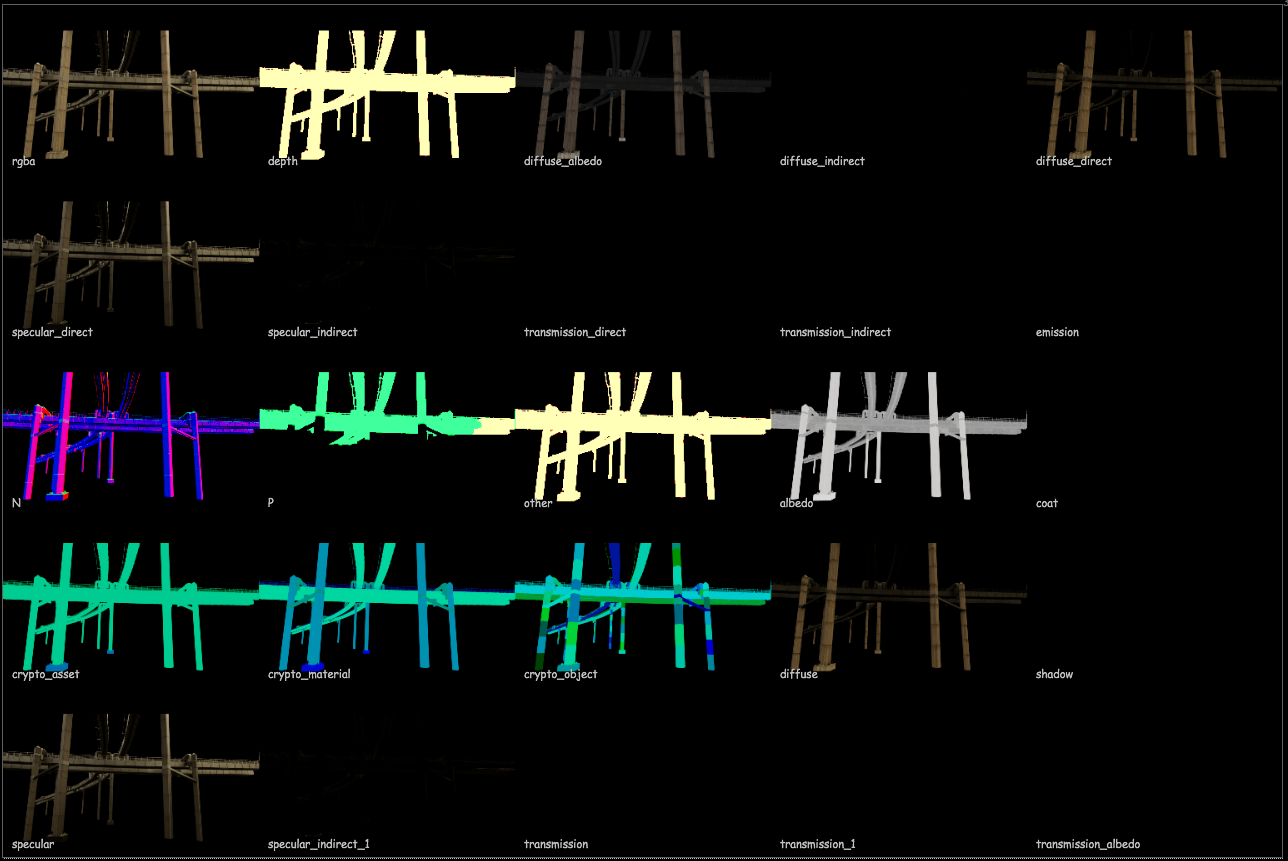
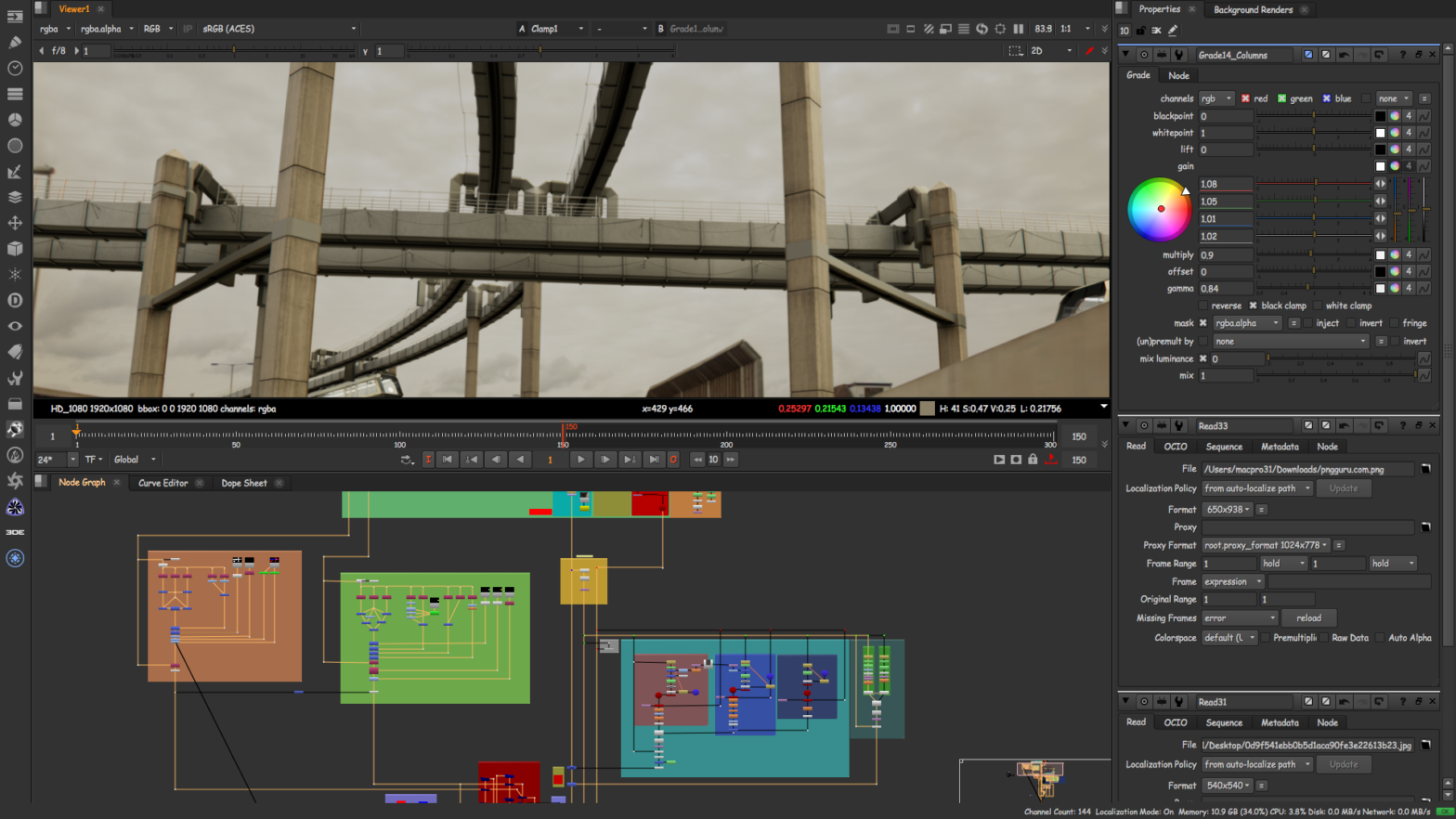
This blog post is about the CG rebuild process in Nuke. All the rendered elements with respective AOVs were used to rebuild the final beauty pass. Below are images of all the AOVs displayed using the LayerContactSheet node inside Nuke. I added some additional passes as opposed to the final render from VX5001 – 3D for Visual effects, namely Cryptomatte passes and a Deep pass. I also turned off global motion vectors for camera motion blur, as this feature was not working as expected.
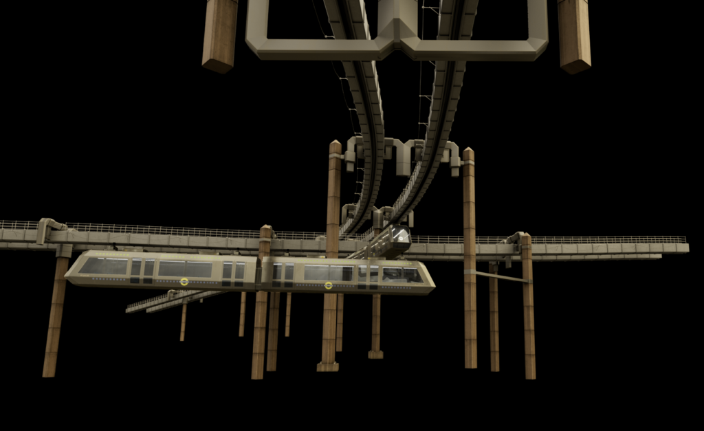
These node graphs depict the setup for both train and the track rebuild. To avoid having to use holdout mattes, I rendered my passes in deepEXR from Arnold, which made the difficult compositing a bit simpler and helped me to add more specific effects into my composition.
Deep Merge graph
This graph shows the compositing process using deep – the CG rebuild outputs are piped in to DeepRecolor nodes, which recolor the deep data into whatever the input is.
In this module, we picked up the rendered elements from 3D for Visual Effects. This includes all render passes, footage and match-moved 3D camera data from 3DEqualizer. The entire module was structured for us to revise skills learned in the first year and then learn a substantial amount of new techniques and industry-standard workflows.
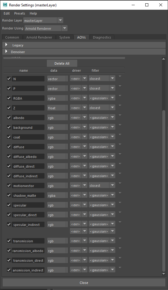
For the final render, we were instructed to use these AOVs (Arbitrary Output Variables) as the minimum requirement: Beauty (RGBA), Direct Diffuse, Indirect Diffuse, Direct Specular, Indirect Specular, Ambient Occlusion, Masks and Alpha for all geometry. Below are all AOVs I have used with my render in Arnold.
AOVs from Maya Arnold
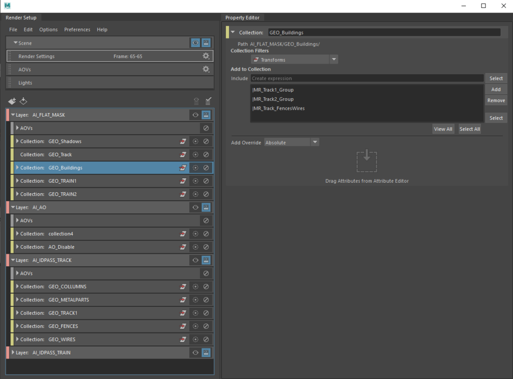
Render layers
These are all render layers I used for rendering the final product. There is a Beauty pass which includes all AOVs, Ambient Occlusion Layer, Mask Layer from proxy geo I created in Maya and ID Pass render layers for both the track and the train separately. Every render layer other than the main render layer had all the extra AOVs disabled, except for the RGBA output. All the AOVs and render layers were rendered as merged openEXR image sequences in ACEScg colourspace, and to my pleasant surprise, totalled roughly about 20GB of disk space.
All render layers I used for final submission
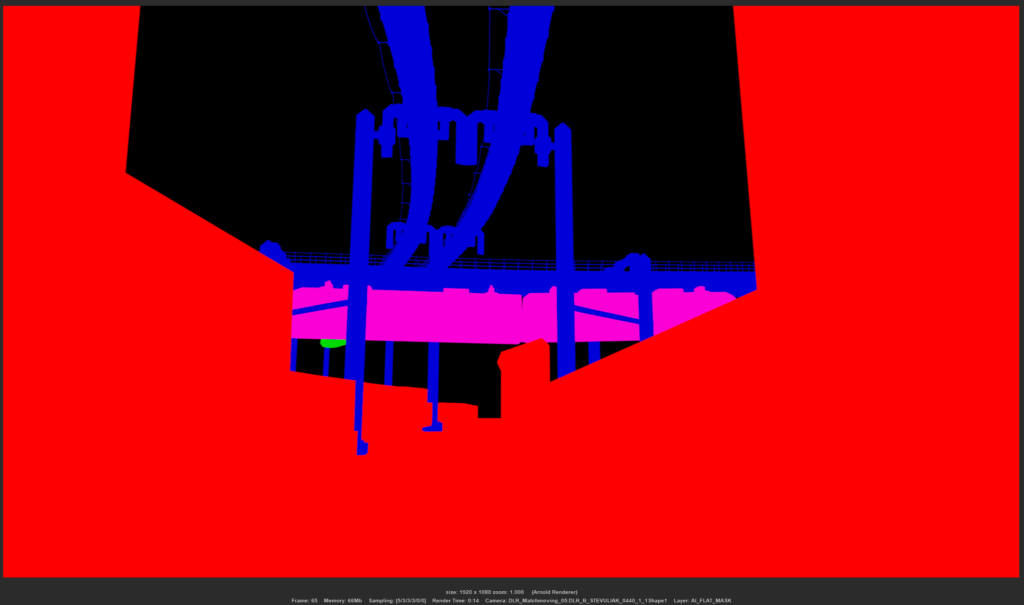
Flat Mask render layer for slap comp
Ambient Occlusion render layer
Track ID Pass render layer
Train ID Pass render layer
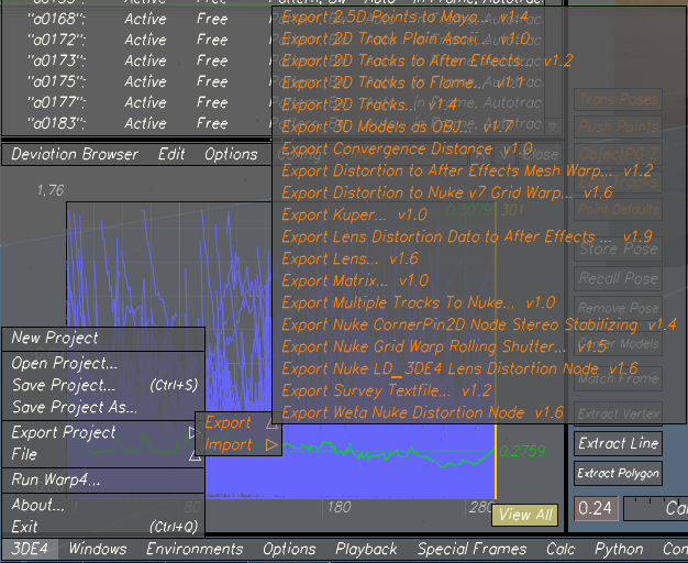
Final Data Export
From 3DEqualizer, I exported the LD_3DE4 node for Nuke along with a Nuke script with all the tracking points and 3D camera.
3DEqualizer data export
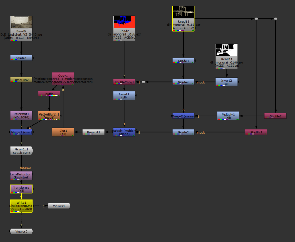
Slap comp
Slap comp node graph
Motion Vectors Fix
I ran into problem trying to render motion blur using my motionvectors. The vectors from Arnold rendered the blur in wrong direction, a fix to this issue is explained in the link below.
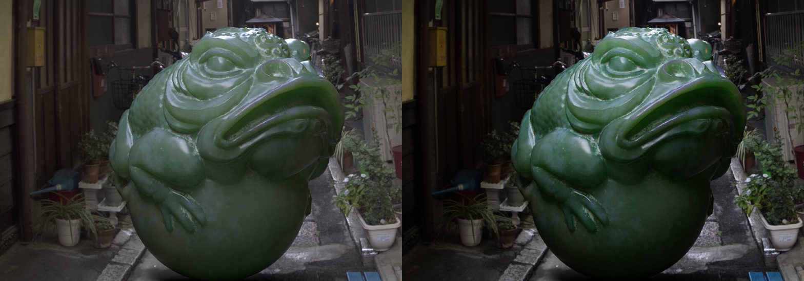
This blog post will guide you on how to set up Academy Color Encoding System in Autodesk Maya, Substance Painter and Nuke. ACES is mainly handled by OpenColorIO, a colour management solution which makes setting up projects for ACES easy across all operating systems and applications.
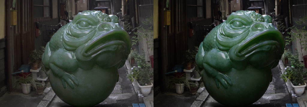
Before and after image using ACES in Substance Painter
“OpenColorIO (OCIO) is is a complete color management solution geared towards motion picture production with an emphasis on visual effects and computer animation. OCIO is compatible with the Academy Color Encoding Specification (ACES) and is LUT-format agnostic, supporting many popular formats. OpenColorIO is natively supported in commercial applications like Katana, Mari, Nuke, Silhouette FX, and others.” – OpenColorIO website.
Before we start, we will look at the basic theory behind colour management.
In order for the image to be displayed properly on different devices, colour spaces were created. sRGB is among one the most widely used today – on smartphones, printers and others. It has a gamma of approximately 2.2, as opposed to Linear, with a gamma value of 1. There are many different colour spaces, such as Rec.709 (Used for 1080p HDTV Content) and Rec.2020 (4K UHDTV Standard Dynamic Range Content.) Not all colour spaces share the same gamma and/or gamut. Wikipedia article about colour spaces and their uses.
Managing colours with ACES means that different colour spaces will be converted into one single colour space. This is made possible by using colour space transforms.
Input Device Transform (IDT) – Color conversion from input material. More properly called an Input Transform. (for example sRGB to ACEScg)
Reference Rendering Transform (RRT) – Colour transformation from scene-referred (ex. ACEScg) to display-referred space (ex. sRGB), using an S-shaped tone curve, image preparation for output.
Output Device Transform (ODT) – Transforms to an output device, a transformation such as sRGB, Rec. 709, DCI-P3, Rec.2020.
In practice, the RRT and ODT are combined and called an Output Transform.
ACES contains different colour spaces, we will look at the main ones:
ACES 2065- 1 – This is a wide-range Linear colour space, with a larger coverage than the human eye, so it is used for archival copies and transfer of material between departments.
ACEScc and ACEScct – Logarithmic colour spaces intended for grading and colour correction.
ACEScg – This is a Linear space for working with CG/VFX. This is the space you need to use as the main colour space for working with colour set-up and light in your rendered images. More information is available here.
Full Arnold workflow post here. Official Maya guides to ACES and transforms here.
Setting up ACES
After downloading the ACES configuration files, extract them on your C: or another drive. (X: for Escape Studios)
ACES as a global environment variable
It is possible to use the ‘OCIO’ environment variable pointing to the ‘config.ocio’ file. This will be picked up by the majority of DCC applications, including Houdini, Nuke, Katana, Mari and others.
ACES in Maya
Start Maya and create a new project.
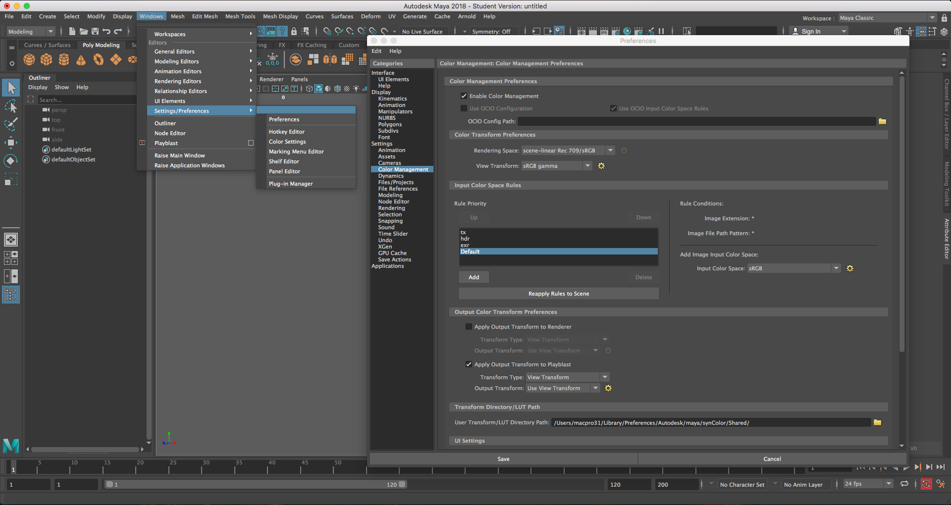
Open the Preferences window, (Windows – Settings/Preferences – Preferences) and go to the colour management tab.
Color Management Settings tab
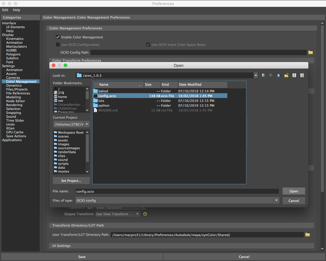
Under Color Management Preferences, set the “OCIO Config Path” to the path you extracted the ACES configuration files to. The file the path has to be set to in our case is called “config.ocio”.
ACES OCIO config file
After setting this, make sure to click check on the “Use OCIO Configuration” checkbox. The configuration will then take a few seconds to load.
Finally, we want to set our default Input Color Space to transform to raw, as we will mostly be using Raw (Linear) images exported from Substance Painter.
Input Color Space Rule
Do not forget to set your colour space transforms properly! Most images you download or use are encoded using sRGB. Info channels (roughness, metalness, or AOVs) are linear. Image plane sequences should be set to sRGB unless you have converted them to ACES or other colour space in Nuke.
ACES in Substance Painter
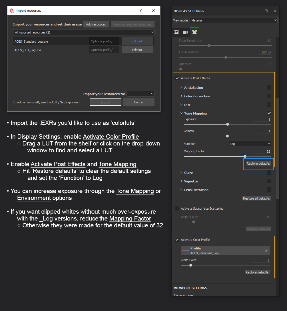
Using ACES in Substance Painter merely a matter of Reference Rendering Transform. The workflow I will be showing you transforms how the viewport in Substance Painter displays your textures. This means that even after you completed your texturing work in Substance Painter without configuring it, you will still be able to fully implement ACES into your workflow. Extract the files downloaded from Gumroad and drag them into the Substance Painter window, import them as ‘colorluts’ to your shelf, so you don’t have to import them every time.
Enabling transform in Substance Painter
Substance Painter exports Base Color textures in sRGB. All other textures are exported in Linear (raw). When bringing Base Color maps into Maya, use input colour transforms (srgb_texture or Output_sRGB) instead of gamma correction, as these transforms are more accurate.
Other software
Other software, such as Adobe CC Apps or Nuke have colour management configurations natively supported. It is only needed to enable them and set them correctly.